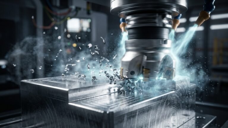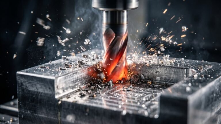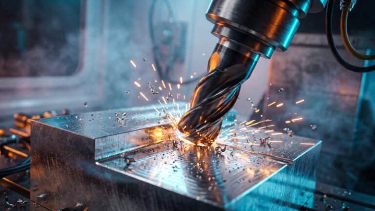
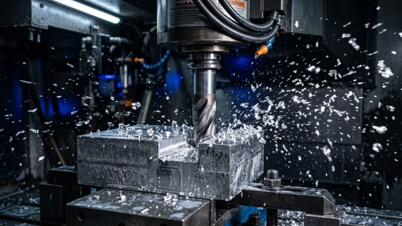
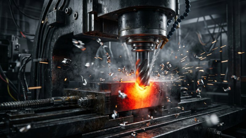
What exactly is CNC milling and how does this advanced technology successfully transform raw material blocks into highly precise, custom components?
CNC milling is an automated subtractive manufacturing process that uses computer-controlled rotating cutting tools to progressively remove material from a solid workpiece. It operates by converting digital 3D CAD designs into machine-readable G-code, which dictates the precise multi-axis movements of the cutting tool and the workpiece to shape the final part with extreme accuracy and repeatability.
The Step-by-Step CNC Milling Process
What exact steps does a CNC machine follow to turn a raw block of metal into a finished part?
The CNC milling process operates through four distinct phases: designing a digital 3D CAD model, translating that geometry into machine-readable G-code using CAM software, physically setting up the machine and workholding devices, and finally, executing the subtractive cutting operation to precisely shape the raw material.

Step 1: Designing the 3D CAD Model
Every successful milling operation begins in the digital realm. Engineers utilize Computer-Aided Design (CAD) software to create a highly accurate 3D model of the desired part. Therefore, this CAD file serves as the absolute blueprint for the entire project.
Why is this initial digital accuracy so critical? Because a CNC machine executes commands precisely without independent judgment. It will blindly replicate the exact dimensions provided. Industrial aerospace designs, for instance, routinely require CAD models built to tolerances of 0.0001 inches. Once the 3D design is complete, engineers export the file into standard formats like STEP or IGES. These specific formats ensure seamless data transfer to the manufacturing software in the next step.
Step 2: Translating the Model into CAM and G-Code
Next, the digital blueprint must be converted into physical instructions. The CAD model is imported into Computer-Aided Manufacturing (CAM) software. The CAM system analyzes the part’s geometry. Subsequently, it determines the most efficient machining strategy and generates precise toolpaths.
But how does a mechanical machine read these digital paths? The CAM software translates the toolpaths into G-code. G-code is the standard programming language of CNC equipment. It dictates exact feed rates, spindle speeds, and coordinate movements.
“G-code bridges the critical gap between digital human design and physical mechanical execution.”
Think of G-code like the legacy punched tape used in early numerical control (NC) mills. It provides a rigid, step-by-step sequence of coordinates that strictly governs every mechanical movement, ensuring the spindle moves exactly where the software plotted the path.
| Digital Stage | Core Function | Primary Output |
|---|---|---|
| CAD | Designs part geometry digitally | 3D Solid Model (STEP/IGES) |
| CAM | Determines the machining strategy | Optimized Toolpaths |
| G-Code | Commands physical machine actions | Alphanumeric Instructions |
Step 3: Preparing the Machine and Workholding
Before any metal is cut, an operator must physically prepare the CNC mill. First, they must secure the raw material block, known as the workpiece. Operators use heavy-duty workholding devices such as vises, step clamps, or custom-machined fixtures.
Proper workholding is absolutely essential. It prevents dangerous vibrations during heavy cutting. Even minor vibrations can completely ruin a part’s surface finish or shatter carbide end mills. Second, the operator loads the required cutting tools into the machine’s automatic tool changer. Finally, they establish a “zero point” on the machine. Consequently, the CNC mill knows exactly where the raw block is located in physical space.
Step 4: Executing the Subtractive Cutting
Finally, the automated subtractive process begins. The machine’s spindle rotates the cutting tool at extremely high speeds. Meanwhile, the machine moves the tool along the programmed G-code coordinates.
First, the machine performs roughing passes. These aggressive cuts remove large volumes of material very quickly. Next, the machine switches to finishing passes. Finishing passes use lighter cuts to achieve the final dimensions and a smooth surface. During this entire stage, high-pressure coolant is flooded over the cutting area. Coolant reduces intense friction heat and flushes away sharp metal chips. In fact, industry tooling data shows that optimizing coolant delivery can extend cutting tool life by up to 30%. The machine stops once the code completes, leaving behind a perfectly accurate component.
The Physical Mechanics of CNC Milling Axes
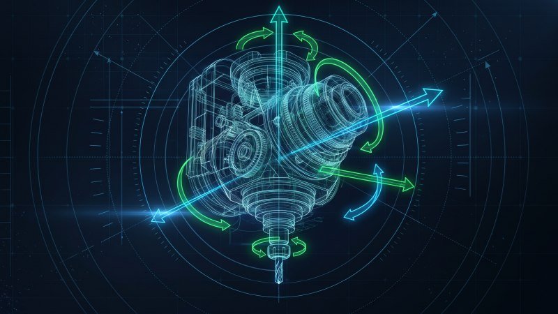
The physical axes of a CNC machine dictate the complexity of the parts it can create. These axes represent the independent directions in which the cutting tool or the workpiece can move. Three-axis machines move along linear X, Y, and Z planes, while advanced four-axis and five-axis machines introduce rotational movements to cut complex geometries without manually repositioning the raw material.
Standard 3-Axis Machining
Three-axis milling is the most common form of CNC machining. First, the cutting tool moves along three linear directions. Specifically, it moves left to right on the X-axis. Next, it moves front to back on the Y-axis. Finally, it moves up and down on the Z-axis. Therefore, the cutting tool only addresses the top face of the workpiece.
Industry data indicates that 3-axis machines still handle roughly 70% of standard mechanical components. This is primarily due to lower machine costs and simpler programming. For instance, creating a flat engine mounting bracket is perfect for a 3-axis machine. However, 3-axis machining has a major limitation. It cannot cut under overhangs or reach the sides of a part.
To reach a side face, an operator must physically stop the machine. Then, they must manually rotate the metal block in the vise. Think of traditional drill press operations: a drill only moves straight down into a flat plate. A 3-axis mill operates with similar top-down restrictions, just with automated side-to-side movement. Ultimately, this manual repositioning increases production time and risks alignment errors.
Advanced 4-Axis and 5-Axis Machining
What happens when a part requires features on multiple sides? This is where advanced 4-axis and 5-axis machines become strictly necessary. A 4-axis machine includes the standard X, Y, and Z movements. Additionally, it adds a rotational axis. Usually, this is the A-axis, which rotates the workpiece around the X-axis.
Consequently, 4-axis machines can flip the part automatically during the cycle. They are excellent for cutting cylindrical parts. Furthermore, 5-axis machining adds a second rotational axis. This is typically the B-axis or C-axis. Because of these two rotational axes, the cutting tool can approach the workpiece from almost any conceivable angle. Therefore, 5-axis machines can create highly organic shapes. For example, aerospace manufacturers strictly rely on 5-axis machines to cut complex titanium turbine impellers.
“Reducing manual part flipping directly eliminates human setup errors and drastically improves final part accuracy.”
These advanced machines offer a “done-in-one” setup. Specifically, the machine cuts five sides of a block in a single continuous operation.
| Axis Type | Movement Capabilities | Ideal Applications | Setup Efficiency |
|---|---|---|---|
| 3-Axis | X, Y, Z (Linear only) | Flat brackets, simple plates | Low (Requires manual flipping) |
| 4-Axis | X, Y, Z + 1 Rotation | Cylinders, multi-sided drilling | Medium (Automated rotation) |
| 5-Axis | X, Y, Z + 2 Rotations | Aerospace impellers, organic parts | High (Done-in-one setup) |
Primary Cutting Techniques During Operation
What specific cutting methods do machinists use to shape raw metal during a milling operation?
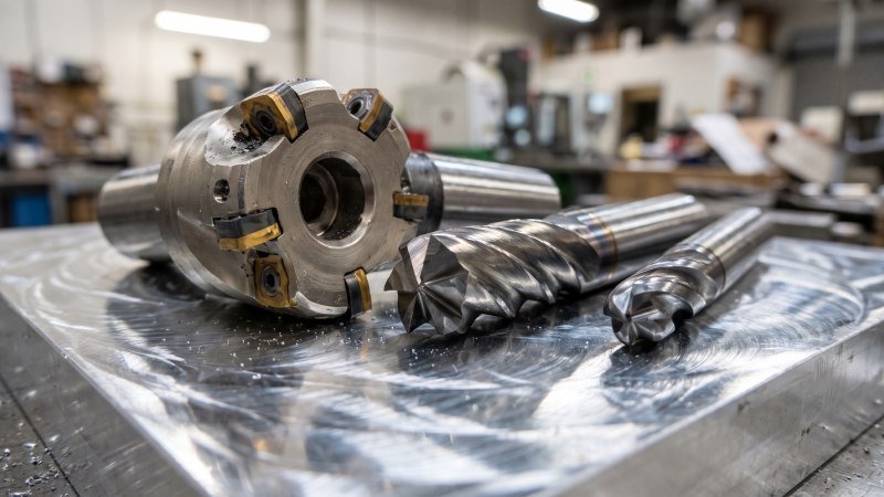
CNC milling operations rely on three primary subtractive techniques. First, face milling creates extremely flat, smooth surface finishes. Next, peripheral milling cuts deep slots and side profiles. Finally, form milling produces complex, customized geometric contours. Consequently, each specific method requires unique cutting tools and distinct machine orientations to successfully remove material.
Face Milling
Face milling is the most common technique for flattening raw stock. Specifically, the machine positions the cutting tool’s rotational axis perpendicular to the workpiece surface. Therefore, the cutting action happens on the flat face of the tool.
Furthermore, the tool utilizes multiple cutting inserts along its outer edge. These sharp inserts shear away the metal smoothly. For instance, automotive manufacturers heavily rely on face milling to deck engine blocks. This process is very similar to how a large rotary fly cutter surfaces a cast iron cylinder head in a traditional engine rebuilding shop.
Why is this method so popular? Primarily, it produces exceptional surface finishes. In fact, modern face mills can consistently achieve surface roughness values below 32 Ra (microinches). Additionally, this rigid technique allows for aggressive material removal without causing dangerous tool deflection.
Peripheral Milling
Conversely, peripheral milling positions the cutting tool’s axis exactly parallel to the machined surface. Thus, the cutting action occurs entirely along the outer circumference, or periphery, of the tool.
Typically, machinists use this method for cutting deep slots, forming gear teeth, or profiling outside edges. To execute this, the machine drives an end mill or a slab mill sideways through the material. During this specific operation, operators must choose between two distinct feed methods: conventional milling or climb milling.
In climb milling, the cutter rotates in the exact same direction as the material feed. Consequently, industry machining data shows that climb milling can extend cutting tool life by up to 50% compared to conventional milling. Ultimately, it reduces friction heat and efficiently pulls metal chips out behind the cutter.
Form Milling
Form milling tackles highly specialized, non-linear shapes. In this specific technique, the cutting tool itself possesses the exact inverse shape of the desired final contour. Therefore, the tool physically imparts its unique geometry directly onto the raw material.
For example, cutting a complex spur gear requires a specialized involute gear cutter. The machine strictly drives this custom-shaped tool straight through the metal blank. Generally, form milling operates slower than face or peripheral milling because the large contact area can cause chatter if pushed too fast. However, it completely eliminates the need for complex multi-axis interpolation.
“Using a custom form tool guarantees perfect geometric repeatability across thousands of specialized production parts.”
| Milling Technique | Tool Orientation | Primary Machining Function | Common Cutting Tool |
|---|---|---|---|
| Face Milling | Perpendicular to part | Flattening broad top surfaces | Shell mill, face mill |
| Peripheral Milling | Parallel to part | Cutting slots and side profiles | End mill, slab mill |
| Form Milling | Dependent on contour | Creating custom complex shapes | Gear cutter, radius mill |
Conclusion
Understanding the step-by-step CNC milling process, the physical mechanics of multi-axis machines, and the distinct cutting techniques provides a clear view into modern manufacturing. By leveraging accurate CAD/CAM data and utilizing the appropriate milling methods, raw materials are transformed into complex, high-tolerance components efficiently. Whether your project requires basic 3-axis flat brackets or complex 5-axis organic geometries, choosing the right machining strategy ensures optimal surface finishes and dimensional accuracy.