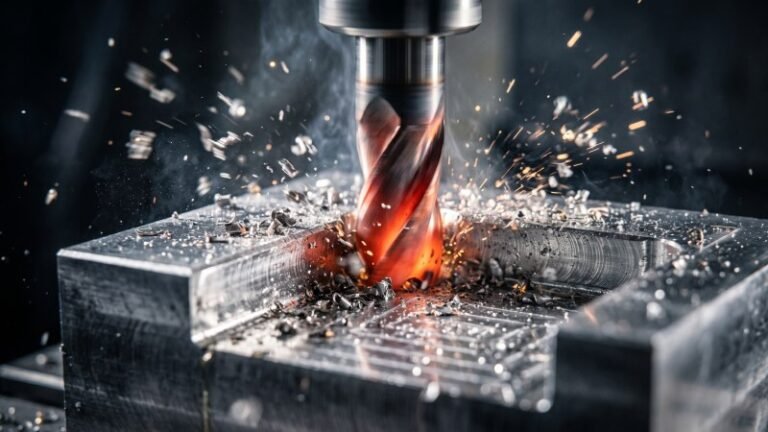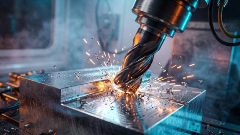
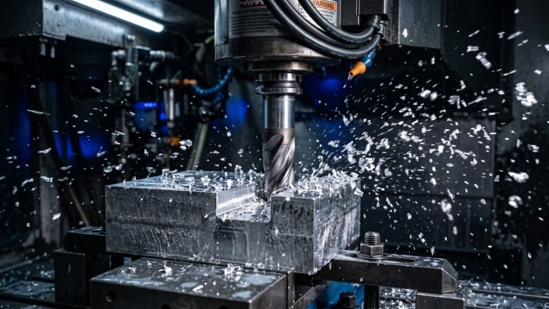
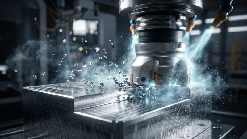
What exactly is face milling, and what purpose does a face mill cutter serve in a modern machine shop?
Face milling is a core CNC machining process that uses a specialized milling cutter with multiple cutting edges to create perfectly flat surfaces on a workpiece. A face mill cutter is primarily used to rapidly remove bulk material from large areas, square up raw stock, and achieve superior surface finishes by operating perpendicularly to the face of the material.
Primary Applications of Face Mill Cutters
What exactly are the main uses of a face mill cutter in CNC machining?
Face mill cutters are primarily used in CNC machining to quickly remove large amounts of material, create perfectly flat surfaces, and achieve superior surface finishes on raw metal stock. Because of their large diameter and multiple cutting edges, they quickly flatten broad areas and prepare workpiece datums much faster than other tools.
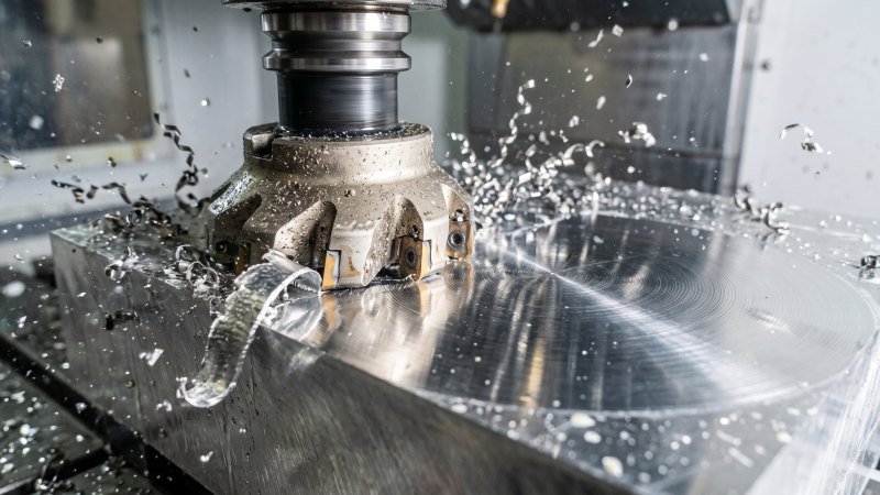
Rapid Material Removal on Large Flat Surfaces
When a machinist looks at a raw metal block, the first goal is often to clear away the top layer. How can you do this without wasting hours? You use a face mill.
First, these tools are built for a high Metal Removal Rate (MRR). Consequently, they can strip away thick layers of steel or aluminum in very few passes. A typical face mill features a wide cutting diameter. For example, standard job shop diameters often range from 2 to 8 inches. Therefore, the tool covers a massive area in a single sweep.
Think of it like using a massive broad-faced grinding wheel to flatten a welded plate, instead of using a tiny rotary burr. You cover much more ground instantly.
As a result, cycle times drop significantly. In fact, using a 4-inch face mill on a 10-inch wide block takes only a few quick passes. In addition, the multiple cutting inserts share the heavy load. This prevents the CNC machine spindle from stalling under deep cuts. Ultimately, this makes the entire roughing process highly efficient.
Achieving High-Quality Surface Finishes
Beyond simply removing bulk material, face milling is famous for leaving a mirror-like finish. Why is this surface quality so important? A smooth finish is critical for sealing surfaces or mating parts.
Generally, face mills cut on the outer edge. However, they also have a slight flat area on the bottom of the inserts. This bottom edge acts as a wiper. Consequently, it physically irons out the metal as the tool spins.
Furthermore, the wide and rigid body of the cutter greatly reduces vibration. Less vibration directly equals fewer chatter marks left on the metal.
Here is a quick look at typical surface finishes achieved in manufacturing:
| Machining Process | Typical Surface Roughness (Ra) | Best Use Case |
|---|---|---|
| Rough Face Milling | 125 to 250 microinches | Initial material sizing |
| Finish Face Milling | 32 to 63 microinches | Mating surfaces, engine block decks |
| Precision Grinding | 8 to 16 microinches | High-friction bearing surfaces |
Clearly, a proper finish pass with a face mill bridges the gap between rough cutting and expensive grinding. Therefore, shops often rely on it to meet strict blueprint tolerances without moving the part to a separate grinding machine.
Squaring and Facing Raw Stock
Before any complex pockets or drilled holes can be made, a part needs a flat starting point. This vital initial step is called facing raw stock.
First, raw cast iron or extruded aluminum blocks are rarely perfectly flat when they arrive. Therefore, a face mill is used to machine the first perfectly flat side. This newly cut side becomes the primary datum. A datum is simply a flat reference surface used to measure all other part dimensions.
Once the top is completely flat, the machinist flips the part over. Next, they mill the remaining sides to create a perfectly square block.
Is it really necessary to square the stock first? Absolutely. If the raw material is warped, the final finished part will fail inspection.
Moreover, the large diameter of the cutter ensures the entire surface is cut on the exact same plane. There are no uneven steps or ridges left behind. Consequently, the workholding vises can grip the squared block securely for all remaining CNC operations.
Common Types of Face Milling Cutters
What are the different types of face mill cutters used on a CNC machine?
The most common types of face milling cutters are indexable face mills, shell mills, and fly cutters. Indexable face mills feature a reusable steel body with replaceable carbide inserts for heavy production. Shell mills are arbor-mounted cutters used for medium-duty facing. Meanwhile, fly cutters use a single rotating tool bit to achieve ultra-smooth, mirror-like finishes on large flat surfaces.
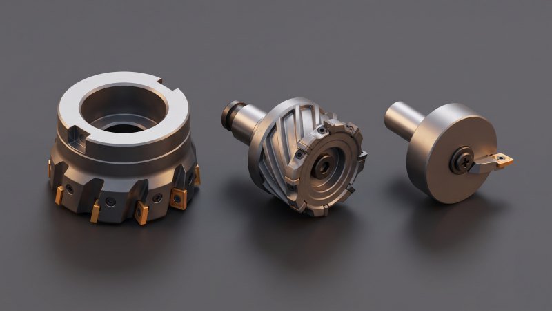
Indexable Face Mills
Indexable face mills are the undisputed workhorses of modern machine shops. First, they consist of a heavy steel tool body. Next, small, replaceable carbide inserts are screwed tightly into the outer edges of this body.
Therefore, when a cutting edge gets dull, the machinist does not throw the tool away. Instead, they simply unscrew the insert and rotate it to a fresh, sharp edge. This concept is exactly like using a standard turning tool on a CNC lathe; you only replace the small cutting tip, not the entire heavy tool holder.
Why is this modular design so important? It drastically lowers tooling costs. In fact, replacing carbide inserts reduces long-term tooling expenses by up to 60% compared to buying solid cutters.
Furthermore, these tools are highly versatile. Because you can swap inserts easily, you can cut soft aluminum in the morning and hard stainless steel in the afternoon. You simply change the carbide grade while using the exact same tool body.
Shell Mills
Shell mills are another staple in the manufacturing world. Unlike standard end mills that fit directly into a collet, a shell mill has a hollow center. Consequently, it mounts onto a separate, sturdy tool holder called an arbor.
Generally, traditional shell mills have multiple cutting teeth carved directly into their solid outer shell. However, many modern versions also utilize indexable inserts. The defining feature is the arbor-mounting system. Because they mount broadly on an arbor, they offer exceptional rigidity.
This rigidity prevents the tool from bending or vibrating during a heavy cut. Therefore, shell mills are perfect for medium-duty facing tasks. They typically range from 1.5 inches to 6 inches in diameter. As a result, they provide a perfect balance on the shop floor. They remove material quickly, but they do not demand the massive machine horsepower that a giant 10-inch indexable face mill would require.
Fly Cutters
Why would anyone use a tool with only one cutting edge when they could use ten? The answer is simple: flawless surface finish.
A fly cutter consists of a central cylindrical body holding a single, single-point cutting tool. As the machine spindle spins, this single cutter sweeps in a large circle across the metal. Think of it like a boring bar used on a lathe, but instead of cutting the inside of a round hole, it sweeps across a wide, flat plane.
Because there is only one cutting point, there is absolutely zero height variation. In a multi-tooth cutter, if one tooth is even 0.0001 inches higher than the rest, it leaves a visible scratch on the metal. A fly cutter completely eliminates this problem. Consequently, it delivers a flawless, mirror-like finish.
However, there is a distinct trade-off. Since only one tooth is doing all the work, the CNC machine must feed the tool across the part very slowly. Therefore, fly cutters are exclusively used for light finishing passes. They are never used for heavy material removal.
To make choosing the right tool easier, here is a quick comparative breakdown:
| Cutter Type | Number of Cutting Edges | Material Removal Speed | Best Surface Finish | Primary Use Case |
|---|---|---|---|---|
| Indexable Face Mill | Multiple (Replaceable) | Very Fast | Good | Heavy roughing and high-volume production |
| Shell Mill | Multiple (Solid or Inserts) | Moderate to Fast | Good | Medium-duty facing with good tool rigidity |
| Fly Cutter | Single (Adjustable) | Very Slow | Excellent (Mirror-like) | Final finishing passes on wide, flat surfaces |
Face Milling vs End Milling
How exactly do face milling and end milling differ in a CNC machine shop?
Face milling and end milling differ primarily in tool design, cutting mechanics, and overall purpose. Face milling uses a wide tool to cut flat across a top surface, providing rapid material removal for large areas. Conversely, end milling relies on a long, cylindrical tool that cuts with both its end and sides, making it essential for carving deep pockets, slots, and complex part profiles.
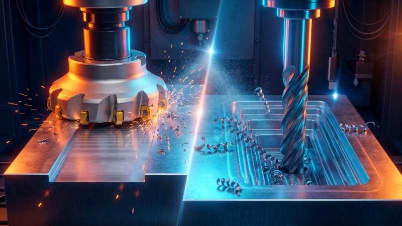
Tool Structure Differences
First, look at how the tools are built. A face mill is generally short, wide, and thick. It consists of a heavy steel body holding multiple replaceable cutting inserts around its outer edge. This wide stance provides massive rigidity.
On the other hand, an end mill is typically a long, solid cylinder. Most modern end mills are ground from a single piece of solid carbide or high-speed steel (HSS). Instead of flat inserts, they feature deep spiral grooves called flutes running up their sides.
Think of the structural difference like this: a face mill acts like a large, rigid boring head designed purely to sweep across a wide plane. Meanwhile, an end mill functions much like a standard twist drill that has been specifically reinforced to cut sideways through solid metal. Consequently, end mills are much smaller in diameter, usually ranging from 1/8 inch to 1 inch. Face mills, however, frequently exceed 3 inches across.
Machining Orientation and Cutting Edges
Next, consider how each tool actually attacks the metal. In face milling, the tool rotates on an axis that is strictly perpendicular to the workpiece. The primary cutting action happens at the very outside corner of the tool inserts. Meanwhile, the flat bottom edge gently sweeps over the metal to smooth it out.
End milling operates quite differently. An end mill cuts aggressively with both its bottom tip and its fluted sides. Therefore, it can plunge straight down into a solid block of aluminum and then move horizontally to carve out a shape.
Because of this, an end mill easily handles a heavy radial depth of cut. It can carve deep along the side of a part. In contrast, a face mill is strictly limited to shallow vertical depths, but it takes massive horizontal step-overs.
Application Suitability
When should a machinist choose one over the other? The choice depends entirely on the blueprint geometry. You use a face mill to flatten a broad surface as quickly as possible. However, you cannot use a face mill to cut a narrow groove or a deep internal cavity.
Therefore, end mills step in for the intricate work. Machinists rely on end mills to machine deep pockets, cut keyways, and trace complex outside profiles.
To make the selection process simple, look at this direct comparison:
| Feature | Face Milling | End Milling |
|---|---|---|
| Primary Function | Flattening large top surfaces | Cutting pockets, slots, and profiles |
| Primary Cutting Area | Outer corners and bottom wiper | Bottom tip and side flutes |
| Material Removal Strategy | Wide, shallow cuts | Narrow, deep cuts |
| Plunging Ability | Cannot plunge straight down | Can plunge directly into solid stock |
Ultimately, these two tools work together as a team. A shop will first use a large face mill to flatten the raw block. Afterward, they will load an end mill to carve out the precise internal details of the final part.
How to Perform Face Milling Perfectly
How can machinists optimize the face milling process for perfect results?
Performing face milling perfectly requires strict control over tool positioning, precise feed and speed calculations, and the correct milling direction. Machinists must optimize the cutter engagement width, match the spindle speed to the material, and utilize climb milling to guarantee a flawless finish.

Optimizing Tool Positioning and Engagement Width
How you position the cutter over the metal dictates the success of the entire operation. First, you must never center a face mill directly over the workpiece. If the cutter is perfectly centered, the inserts engage and exit the cut simultaneously on both sides. Consequently, this creates severe harmonic vibration and chatter.
Instead, you should always offset the cutter slightly. Industry best practices recommend an engagement width of about 70% to 80% of the cutter’s total diameter. Therefore, if you are using a 4-inch face mill, you should only cut a path about 3 inches wide.
By offsetting the tool, you maintain a constant cutting load on the inserts. This setup drastically reduces vibration and prevents severe entry shock that occurs when an insert strikes the material dead-center, which can instantly chip or break carbide inserts.
Setting Optimal Feeds and Speeds
Speed and feed rates act as the heartbeat of any machining process. Spindle speed refers to how fast the cutter spins. Meanwhile, the feed rate is how fast the machine pushes the metal into the cutter. If you guess these numbers, you will instantly burn up your tool.
Generally, softer metals require high speeds and high feeds. Conversely, hard metals demand slow speeds but maintain a steady, aggressive feed. If you feed too slowly on hard steel, the tool simply rubs against the metal instead of cutting it. This rubbing generates massive heat and melts the cutter.
To maintain accuracy, machinists rely on specific Surface Feet per Minute (SFM) and Inch per Tooth (IPT) data. Here is a baseline data table for common aerospace and industrial materials:
| Material Type | Typical Surface Speed (SFM) | Feed per Tooth (IPT) | Coolant Strategy |
|---|---|---|---|
| 6061 Aluminum | 2,000 – 4,000 | 0.005 – 0.010 | High-pressure liquid |
| 1018 Mild Steel | 600 – 900 | 0.004 – 0.008 | Dry cutting or air blast |
| Grade 5 Titanium | 150 – 250 | 0.002 – 0.005 | High-pressure liquid |
Ultimately, applying these exact parameters ensures maximum tool life. It also prevents excess heat from warping the final part.
Using Climb Milling for Better Surface Finish
The direction the tool travels across the metal changes everything. In a CNC machine, you should almost always use climb milling. During climb milling, the tool rotates in the same direction as the feed of the workpiece at the point of engagement.
Why is this so important? Climb milling creates a thick-to-thin chip. The insert bites deeply into the metal first, then tapers off to zero thickness as it exits. Consequently, this action gently wipes the surface smooth.
In contrast, conventional milling rubs the metal before it finally bites in. This rubbing creates immense friction. It severely damages the surface finish.
Furthermore, climb milling actually pushes the workpiece down into the holding vise. This downward force maximizes rigidity. In rigid CNC setups, switching from conventional to climb milling routinely increases insert tool life by up to 50%. Therefore, unless you are using a very old manual machine with backlash, climb milling is the ultimate choice for perfect results.
Conclusion
Face milling is an indispensable foundation of modern CNC machining. Whether you are using a massive indexable face mill to rip through raw steel or employing a precise fly cutter for a mirror-like finish, mastering this process sets the stage for every subsequent manufacturing step. By understanding the differences between face and end milling, correctly choosing your tool, and adhering to strict feed and speed parameters, you can drastically reduce cycle times while producing perfectly square, dimensionally accurate parts.