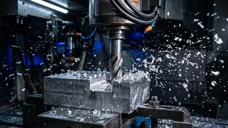
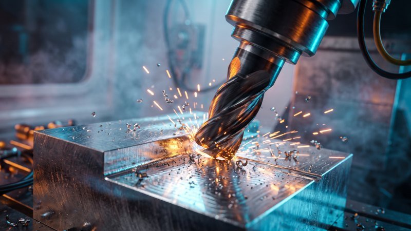
What exactly is milling in the context of modern machining and engineering?
Milling is a fundamental subtractive manufacturing process that uses rotating multi-point cutting tools to gradually remove material from a stationary or slowly feeding workpiece. It is essential in engineering for producing highly accurate, custom-designed parts with complex geometries, flat surfaces, and intricate internal profiles across various industrial applications.
Primary Milling Operations and Techniques
Modern machining relies on several distinct milling operations to shape materials precisely.
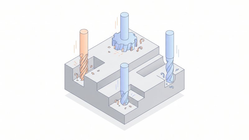
Primary milling operations refer to the specific cutting techniques used to remove material from a workpiece. The main methods include face milling for flat surfaces, peripheral milling for heavy material removal, end milling for versatile shaping, and slot milling for creating channels. Each technique uses specialized rotary cutters to achieve precise dimensions and desired surface finishes in engineering projects.
Face Milling
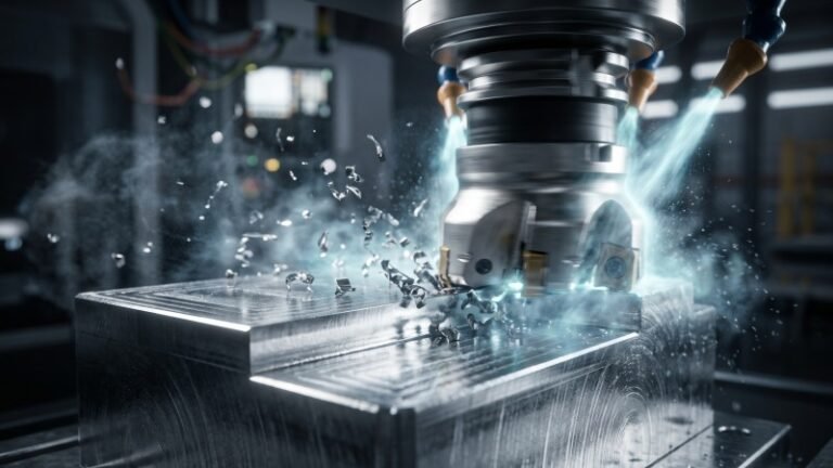
Face milling is primarily used to create flat surfaces on a raw workpiece. Therefore, the cutting tool rotates on an axis that is completely perpendicular to the surface of the part. Have you ever needed to perfectly level a rough block of raw metal? Face milling is the standard solution.
During this operation, the cutting teeth are located mostly on the face of the tool. Consequently, the outer edges perform the heavy material removal, while the face teeth smooth out the surface. Think of this process as being similar to using a large surface grinder to flatten a rough cast iron block. However, face milling removes material significantly faster.
Furthermore, engineers rely on this method for initial raw stock preparation. It consistently achieves excellent surface finishes. For example, standard face milling can easily produce an Ra (Roughness Average) of 0.8 to 1.6 micrometers.
Peripheral Milling
Peripheral milling is often called slab milling in the workshop. In this process, the rotation axis of the cutting tool remains exactly parallel to the surface being machined. Thus, all the active cutting teeth sit on the outside circumference of the cutter.
This technique excels at aggressive material removal. It works best on large, wide metal surfaces. You can compare peripheral milling to a heavy-duty broaching operation. Just as a broach shears a long, straight channel through a part, a peripheral cutter shears away thick layers of material along its broad side.
Additionally, the cut depth determines the size of the chips produced. Engineers usually choose peripheral milling when removing massive amounts of raw metal quickly is more important than achieving a mirror-like finish.
End Milling
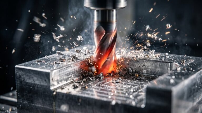
End milling is incredibly versatile. As a result, it is the most common operation in custom parts manufacturing. The cutting tool, called an end mill, has active cutting teeth on both its bottom end and its outside edge.
Because of its specific design, a center-cutting end mill can plunge straight down into solid material. However, to prevent catastrophic tool breakage from bottoming out, professional machinists typically enter the raw stock using helical interpolation or ramping techniques. Afterward, the tool moves horizontally to carve out complex internal shapes. Think of a center-cutting end mill as a highly specialized drill bit that can cut sideways just as easily as it cuts downward.
“End milling remains the backbone of complex component fabrication, bridging the gap between basic hole-making and full 3D contouring.”
This flexibility allows machinists to create highly complex geometric features. Therefore, it is ideal for carving deep pockets, smooth contours, and detailed profiles.
Profile and Slot Milling
Profile milling and slot milling focus on shaping the boundaries and internal channels of a part. Profile milling traces the exact outer or inner edges of a workpiece. Accordingly, it creates the final complex boundary shapes required by mechanical engineering drawings.
On the other hand, slot milling cuts specific internal channels into the material. Engineers frequently design structural parts with internal keyways or T-slots. Machinists use specialized slotting cutters to carve these distinct channels rapidly.
Below is a quick comparison of these primary techniques:
| Milling Operation | Tool Axis Orientation | Primary Machining Goal |
|---|---|---|
| Face Milling | Perpendicular to surface | Flattening broad surfaces rapidly |
| Peripheral Milling | Parallel to surface | Heavy material removal on wide areas |
| End Milling | Both (Plunging & Lateral) | Carving pockets and complex shapes |
| Slot Milling | Perpendicular or Parallel | Creating straight channels and keyways |
Ultimately, selecting the correct cutting operation guarantees dimensional accuracy for the final engineered component.
Types of Milling Machines Used in Manufacturing
What are the primary types of milling machines utilized in modern manufacturing facilities today?
Milling machines are primarily categorized by the specific orientation of their main spindle. The most common types used in manufacturing include vertical milling machines for top-down precision work, horizontal milling machines for heavy-duty material removal, and advanced CNC machining centers that completely automate multi-axis movements for complex engineering projects.
Vertical Milling Machines
Vertical milling machines feature a spindle axis that points straight down. Therefore, the cutting tool operates perpendicularly to the standard worktable. Are you trying to machine the top face of a flat metal plate? A vertical setup is usually your best choice.
You can compare a vertical milling machine to a standard workshop drill press. However, while a drill press only moves a tool up and down, a vertical mill also moves the workpiece side to side. Consequently, it allows machinists to carve complex shapes into the top of the raw stock.
These machines are incredibly common in job shops. They provide excellent visibility for the operator. Furthermore, they are highly effective for plunging cuts. Under standard shop conditions, rigid vertical mills routinely achieve precision tolerances of ±0.001 inches.
Horizontal Milling Machines
Horizontal milling machines utilize a spindle that mounts parallel to the worktable. Instead of cutting from the top, the tool approaches the workpiece from the side.
This horizontal orientation offers a massive mechanical advantage. Think of the robust setup of a heavy-duty engine lathe securing a large steel cylinder. A horizontal mill provides similar rigidity by supporting the cutting tool across a thick, horizontal arbor. As a result, it handles extremely aggressive cuts without excessive vibration.
Moreover, horizontal machines excel at chip evacuation. Because the cutting happens on the side, gravity immediately pulls the metal chips away from the tool. Therefore, operators avoid re-cutting the same chips. In high-volume production, horizontal mills frequently achieve significantly higher material removal rates compared to vertical models during heavy roughing phases.
“Horizontal milling provides unmatched rigidity, making it the undeniable workhorse for high-volume, heavy-duty metal removal.”
Advanced CNC Machining Centers
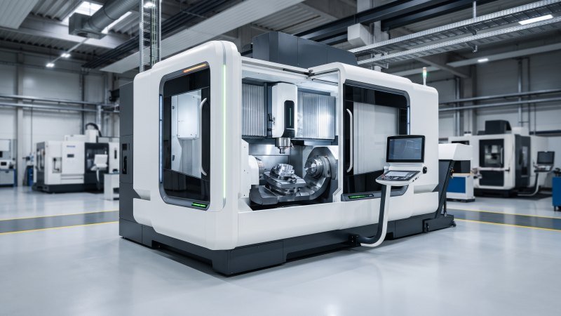
Advanced CNC (Computer Numerical Control) machining centers represent the modern evolution of milling equipment. Unlike manual mills, computers direct every movement of the cutting tool. Consequently, these machines eliminate human error during complex operations.
These advanced centers take the basic vertical or horizontal framework and add extensive automation. For instance, they feature Automatic Tool Changers (ATCs). An ATC can hold anywhere from 20 to over 100 distinct cutting tools. Thus, the machine can swap tools in seconds without operator intervention.
You can liken a CNC machining center to an automated Swiss-type lathe. Both systems strictly follow a pre-programmed digital path (G-code) to execute a flawless, repetitive machining task without manual resets.
Additionally, advanced CNC centers often feature 4-axis or 5-axis capabilities. This means the machine can rotate the workpiece while cutting. Industry production data indicates that utilizing a 5-axis CNC center can reduce total setup times by up to 30%, as it allows machining on five sides of a block in a single setup.
Below is a brief comparison of these primary machine types:
| Machine Type | Spindle Orientation | Key Manufacturing Advantage |
|---|---|---|
| Vertical Mill | Up-and-Down (Vertical) | Excellent operator visibility and simple setup |
| Horizontal Mill | Side-to-Side (Horizontal) | Superior chip evacuation and rigid heavy cutting |
| CNC Center | Variable (Multi-Axis) | Fully automated precision and rapid tool changing |
Commonly Milled Materials and Their Machinability
In engineering, a material is chosen based on the mechanical requirements of the final part, not simply for how easy it is to mill.
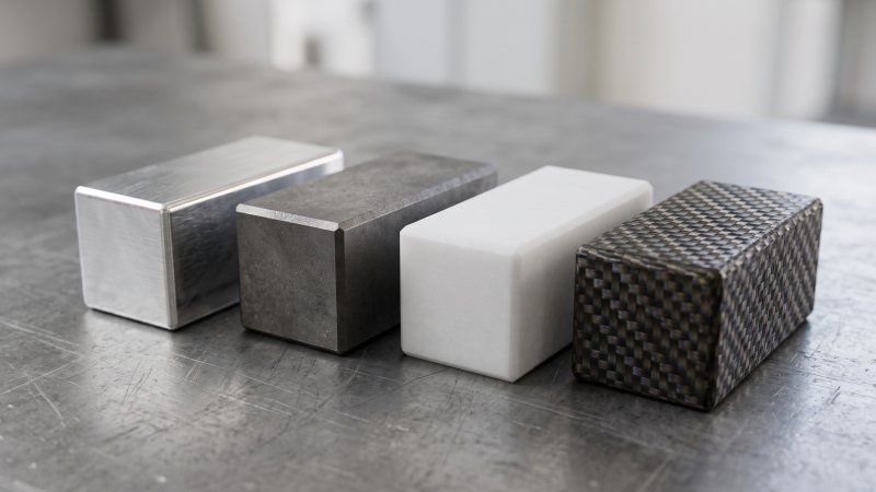
Once an engineer selects a specific metal or plastic for its structural properties, machinists must adapt their tools and speeds to handle its unique cutting characteristics. From highly machinable aluminum and tough titanium alloys to versatile engineering plastics, understanding how different materials behave under a milling cutter—known as their machinability—is crucial for successful manufacturing.
Machining Metals and Alloys
Metals are the absolute foundation of structural engineering. Therefore, they are the most frequently milled materials in any machine shop. However, not all metals behave the same way under a cutting tool. The term “machinability” describes how easily a metal can be cut without wearing down the tool.
Aluminum 6061 is highly popular because it has excellent machinability. Consequently, a milling spindle can spin very fast while cutting it. Standard shop practices show that aluminum can often be milled at surface speeds exceeding 1,000 Surface Feet per Minute (SFM).
On the other hand, titanium alloys and stainless steel present significant challenges. Machining tough titanium is similar to cutting through hardened tool steel. Both materials generate extreme heat at the cutting edge. Furthermore, they can cause rapid tool failure if the speeds are not carefully controlled. Thus, machinists must reduce their cutting speeds to around 150 SFM when milling titanium.
“Managing heat generation and tool wear is the primary focus when milling high-strength metal alloys.”
To handle these tough metals, engineers use specialized carbide end mills. Additionally, they apply constant high-pressure coolant. This prevents the metal chips from welding directly back onto the hot cutting tool.
Working with Plastics and Composites
Modern engineering often requires parts that are lightweight or electrically insulating. As a result, milling plastics and composites has become highly common.
Milling engineering plastics, like Acetal (POM) or PEEK, requires a different approach than metals. Plastics are highly sensitive to heat. If a cutting tool rubs against the plastic instead of slicing it cleanly, the material will simply melt. You can compare milling soft plastics to machining soft brass. Both materials require extremely sharp, highly polished cutting edges to prevent smearing the workpiece.
Furthermore, plastics can warp easily. Despite this, a skilled machinist can hold very tight tolerances. For example, rigid plastics like POM can consistently hold tolerances of ±0.002 inches during standard milling operations.
Composites, such as carbon fiber reinforced polymers, introduce a different problem. The internal fibers are incredibly abrasive. Consequently, they act like sandpaper against standard high-speed steel tools. Shops must use specialized diamond-coated cutting tools to mill composites effectively without premature tool wear.
Below is a quick comparison of material behaviors during the milling process:
| Material Category | Common Examples | Machinability | Primary Milling Challenge |
|---|---|---|---|
| Soft Metals | Aluminum, Brass | Excellent | Clearing stringy chips |
| Hard Metals | Stainless Steel, Titanium | Poor to Fair | High heat and tool wear |
| Engineering Plastics | POM, PEEK, Polycarbonate | Good | Melting and warping |
| Composites | Carbon Fiber, Garolite | Fair | Abrasive wear on cutters |
Milling vs Other Subtractive Manufacturing Processes
How does milling compare to other subtractive manufacturing techniques used in a modern machine shop?
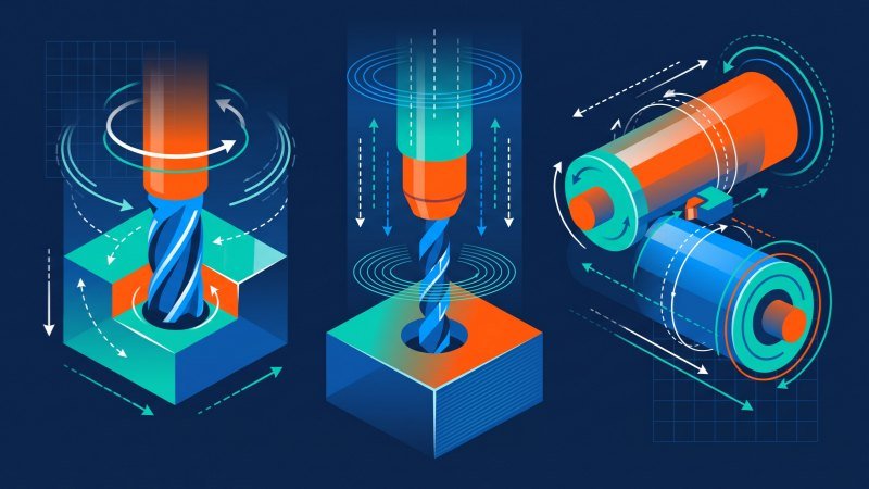
Milling is uniquely defined by using a spinning cutting tool to remove material from a securely clamped, stationary workpiece. Conversely, turning rotates the workpiece itself against a fixed stationary tool, while drilling focuses exclusively on plunging a tool vertically to bore simple holes. Understanding these fundamental mechanical differences allows engineers to select the most accurate and cost-effective machining process for specific component geometries.
Differences Between Milling and Turning
Milling and turning are the two most fundamental subtractive processes. However, their physical operations are completely opposite. What exactly separates them?
During milling, the machine rigidly clamps the metal block. Then, a multi-tooth cutter spins at high speeds to shave away the material. Consequently, milling is perfect for creating flat surfaces, asymmetrical shapes, and deep square pockets.
In contrast, turning requires a lathe machine. Turning spins the actual raw material at high speeds. Meanwhile, a single-point cutting tool remains entirely stationary. The tool slowly presses into the spinning metal to shape it. You can compare turning on a lathe to using a cylindrical plunge grinder. Both processes require the workpiece to rotate continuously on a central axis to achieve perfect roundness.
Therefore, turning is exclusively used to manufacture cylindrical parts. Common examples include engine shafts, round pins, and custom threaded bolts. In practical machining applications, turning a round steel shaft on a lathe is often up to 40% faster than attempting to mill that exact same round shape using circular interpolation on a CNC mill.
“Turning dominates the production of symmetrical, rotating components, while milling remains the ultimate solution for complex, multi-sided block geometries.”
Differences Between Milling and Drilling
Many beginners frequently confuse milling with drilling. Both operations utilize rotating cutting tools. Furthermore, both machines look structurally similar on the shop floor. However, their mechanical capabilities differ drastically.
Drilling performs one very specific task. It drives a drill bit straight down into a solid material. Thus, it only cuts vertically along its own strict axis. The sole manufacturing goal of drilling is to create standard round holes efficiently.
Conversely, milling cuts in multiple directions. A specialized end mill can plunge vertically just like a drill. Afterward, it can immediately travel sideways to carve out a horizontal slot. Think of drilling as a strictly linear operation, much like using a rigid boring bar that only feeds along a single Z-axis. In contrast, milling acts like a multi-axis router that can hollow out entire complex cavities laterally.
Additionally, drilling relies entirely on a specialized pointed tip to shear material. Milling tools use sharp flutes located along their entire outer side edge. As a result, this design allows milling tools to withstand heavy lateral cutting forces that would instantly snap a standard drill bit.
Below is a precise structural comparison of these three core manufacturing processes:
| Machining Process | Tool Motion | Workpiece Motion | Ideal Component Geometry |
|---|---|---|---|
| Milling | Spins and moves laterally | Stationary (or slow linear feed) | Flat planes, slots, pockets, and 3D contours |
| Turning | Stationary (feeds linearly) | Spins rapidly on a central axis | Cylindrical shafts, round discs, and threaded rods |
| Drilling | Spins and plunges vertically | Stationary | Simple internal circular holes |
Conclusion
Milling is an indispensable pillar of modern manufacturing. By utilizing specialized rotating cutters and advanced CNC technology, it transforms simple blocks of raw metal and plastic into the precise mechanical components that drive our world. Understanding the fundamental differences between milling, turning, and drilling—as well as grasping the various milling operations and material characteristics—is essential for anyone learning about subtractive manufacturing. Hopefully, this foundational guide has given you a clear, comprehensive understanding of how the milling process actually works on the shop floor.