
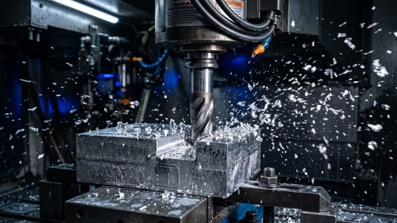

How exactly do you program a perfect circle on a CNC mill using standard G-code?
To program a circle on a CNC mill, you must use circular interpolation commands. G02 is used for clockwise arcs, and G03 is used for counterclockwise arcs. You define the size and position of the circle by providing the machine with a start point, an end point, and either the exact center coordinates using I, J, and K values, or the arc radius using an R value. For a complete 360-degree circle, I and J center coordinates are strictly required.
G02 and G03 Circular Interpolation Commands
What exactly are the G02 and G03 commands used for when machining a part?
G02 and G03 are standard G-code commands used for circular interpolation on a CNC machine. The G02 command directs the cutting tool to move in a clockwise direction. Conversely, the G03 command instructs the tool to travel in a counterclockwise direction. Both commands allow the machine controller to accurately cut arcs and circles by moving two axes at the exact same time.

Programming Clockwise Movements with G02
When you need to cut a curved shape to the right, you will use G02. Therefore, this command tells the machine tool to follow a clockwise path. Have you ever noticed how a tool cuts an outer profile? Often, machinists use G02 for climb milling the outside edge of a solid part.
For example, imagine you are machining a round steel flange. Moving clockwise with standard right-hand tooling ensures the cutting teeth engage the metal properly for climb milling. As a result, this method provides a much smoother surface finish and prevents the tool from rubbing against the material. To achieve this, the machine coordinates the X and Y axes perfectly. Think of this process like using a rotary table on a manual mill. Instead of manually cranking two handles to guess a curve, the CNC controller automatically locks the two axes together. Consequently, it traces a perfect, seamless arc.
To program this successfully, the machine simply needs a starting point. First, you must move the tool to the beginning of the arc using a standard straight-line command (G01). Then, you activate the G02. After that, the controller takes over to drive the tool clockwise toward your programmed end point.
Programming Counterclockwise Movements with G03
On the other hand, G03 handles left-turning, counterclockwise movements. So, why would you choose a counterclockwise path instead? Typically, this choice depends entirely on your specific milling strategy, especially when cutting internal shapes.
For instance, consider hollowing out an internal cavity, such as a deep bearing pocket. You usually need to climb mill the inside walls to clear metal chips effectively and achieve a precise diameter. To do this correctly with standard right-hand tooling, the cutting tool must travel in a counterclockwise circle around the inside wall. Therefore, G03 is the industry standard choice for internal circular pockets. Furthermore, using this correct cutting direction extends your tool life significantly. It also greatly reduces dangerous machine chatter that occurs during conventional milling.
To make the differences clear, review the comparison below:
| Feature | G02 Command | G03 Command |
|---|---|---|
| Tool Direction | Clockwise (CW) | Counterclockwise (CCW) |
| Common Application | Milling outside profiles | Milling inside pockets |
| Standard Milling Strategy | Climb milling (external) | Climb milling (internal) |
| Action Type | Circular Interpolation | Circular Interpolation |
Ultimately, both commands function exactly the same way inside the machine’s computer. The only real difference is the physical direction the spindle travels across the raw material.
Defining the Arc Center Using I J and K
How do you tell the CNC machine exactly where the center of your curved toolpath is located?
To define the arc center, you must use the I, J, and K addresses in your G-code block. These specific letters represent the incremental distance and direction from the tool’s starting point to the exact center point of the arc. By providing these precise coordinate offsets, the machine controller can accurately calculate the required circular toolpath.

Mapping I and J to X and Y Axes
In CNC programming, the letters I, J, and K are directly tied to your primary machine axes. Therefore, you cannot mix them up when writing your program. The controller needs to know exactly which direction the offset applies to.
- I controls the offset distance along the X-axis.
- J controls the offset distance along the Y-axis.
- K controls the offset distance along the Z-axis.
Most of your circular milling happens on a flat, horizontal surface. Specifically, this is the standard XY plane (activated by G17). Consequently, you will use I and J almost exclusively for typical shop jobs. You will only use the K value when you are cutting complex arcs vertically in the XZ or YZ planes.
Think of I, J, and K as the direct companions to your X, Y, and Z axes. Just as X and Y represent the absolute coordinates on your machine table, the I and J commands map the incremental distance along those exact same directional lines to find the invisible center of your arc.
Calculating Incremental Distances from Start Point to Center
How exactly do you figure out the correct numbers for I and J? First, you must remember a critical rule: these values are almost always incremental on standard Fanuc or Haas controllers. This means the measurement starts from where the cutting tool currently sits, not from your main workpiece zero (G54).
To calculate the I value, you must subtract the starting X coordinate from the center X coordinate. Similarly, to find the J value, subtract the starting Y coordinate from the center Y coordinate.
Take a look at this breakdown for clarity:
| Offset Address | Axis Pair | Calculation Formula |
|---|---|---|
| I Value | X-Axis | Arc Center X minus Start Point X |
| J Value | Y-Axis | Arc Center Y minus Start Point Y |
| K Value | Z-Axis | Arc Center Z minus Start Point Z |
Let’s look at a practical shop floor example. Imagine your end mill is resting at a starting position of X2.0 and Y0.0. Next, you want to cut an arc whose center is exactly at X0.0 and Y0.0.
- For I: Center X (0.0) minus Start X (2.0) equals I-2.0.
- For J: Center Y (0.0) minus Start Y (0.0) equals J0.0.
Because these distances rely on direction, they can easily be negative or positive numbers. If the center point is to the left of your tool, the I value is always negative. Alternatively, if the center is directly above the tool, the J value is positive. Getting a single plus or minus sign wrong here is the most common cause of a frustrating “Invalid I, J, or K” machine alarm on the shop floor.
Defining the Arc Radius Using the R Value
How can you program a curved toolpath quickly without calculating complex center point coordinates?
You can define the arc radius directly by using the R value in your G-code block. Instead of finding the exact center point, the R address simply tells the machine controller the size of the curve. The machine’s internal computer then automatically calculates the exact center based on your programmed start and end coordinates. Consequently, this specific method significantly speeds up manual programming for standard corners and simple radii.
Formatting Arcs Under 180 Degrees with Positive R
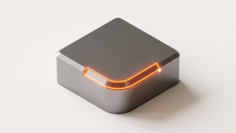
Most curved cuts in a machine shop are relatively small. For instance, you often need to round off a sharp corner on a square steel block. These standard edge breaks are almost always smaller than a half-circle.
When your required arc sweeps exactly 180 degrees or less, you must use a positive R value. Therefore, you simply write the letter R followed directly by the radius dimension. For example, a half-inch corner radius is written simply as R0.5.
Why does the positive sign matter so much? The CNC controller actually sees two possible circular paths between your start and end points. One path is short, and the other path is long. A positive R value explicitly tells the machine tool to take the shorter, more direct path.
Shop Floor Programming Example
Imagine you are climb milling an outer profile. You approach a standard 90-degree corner. To cut a 0.250-inch corner radius, your code will look like this:
G02 X2.0 Y2.0 R0.25
Because the value is positive, the tool seamlessly rounds the corner and continues. Indeed, this is the most common way machinists write simple curves directly at the controller.
Formatting Arcs Over 180 Degrees with Negative R
What happens when your required curve is much larger than a simple half-circle? Sometimes, you must machine a deep, sweeping profile that wraps far around a part. This is exactly where the negative R value becomes critical.
If your arc sweeps more than 180 degrees, you must put a minus sign in front of the radius. For example, you would format the command as R-0.5. As a result, this negative sign forces the CNC controller to choose the longer toolpath around the imaginary circle.
If you forget the negative sign, the machine will usually not trigger an alarm. However, it will automatically cut the short path instead. Consequently, this simple programming typo will instantly ruin your raw workpiece.
To summarize these formatting rules, review the operational data in this quick reference table:
| Arc Sweep Angle | Required R Value Sign | Machine Toolpath Behavior | Common Shop Application |
|---|---|---|---|
| 180 Degrees or Less | Positive (e.g., R1.0) | Takes the shortest path between points | Corner radii, edge breaks, simple fillets |
| More than 180 Degrees | Negative (e.g., R-1.0) | Takes the longest path between points | Deep profile wrapping, partial keyways |
Ultimately, using the R value makes manual programming incredibly fast. You simply need to watch your sweep angles carefully.
Rules for Programming a Full 360 Degree Circle
What is the most reliable way to program a complete 360-degree circle on a CNC machine without causing a system error?
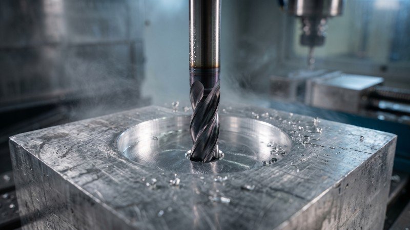
To program a full 360-degree circle successfully, you must explicitly define the center point using I and J commands, or break the operation into smaller segments. A CNC controller requires clear mathematical data to generate a toolpath. Because a full circle starts and ends at the exact same coordinate, specialized formatting rules are strictly required to prevent machine alarms and ruined parts.
Why the R Value Fails for Full Circles
Many operators try to use a simple R value to cut a complete circle. However, this method will always fail. Why does the machine reject this code?
The problem is basic geometry. When you program a full circle, your starting point and ending point are exactly the same. If you only give the machine a radius (R), the controller becomes confused. It sees an infinite number of possible circles that could exist with that specific radius touching that single point.
Think of this like a spot drill plunging straight down into a workpiece. If you command a drill to move from X0 to X0, it simply stays in the exact same hole because there is no distance to travel. Similarly, if you command an R value with identical start and end coordinates, the controller cannot determine which direction to swing the arc out of the infinite possibilities. Consequently, standard Fanuc and Haas controls will instantly trigger a “Radius Error” alarm or simply ignore the command entirely.
Executing a Full Circle Using I and J Format
To cut a complete circle in one smooth motion, you must use the I and J format. This method works perfectly because it explicitly tells the machine exactly where the center point is located.
When writing this block of code, you do not need to state the X and Y ending coordinates. The machine already knows it must return to the start point. You only need to provide the G02 or G03 command alongside the I and J offsets.
For example, imagine your tool is positioned at X2.0 and Y0.0. You want to cut a full circular profile around a center point of X0.0 and Y0.0. Your code will look like this:
G02 I-2.0 J0.0
By providing the exact center distance, the controller locks the axes together. As a result, the spindle sweeps 360 degrees and returns exactly to where it started. Indeed, this is the cleanest and most professional way to mill a full circular feature.
Splitting a Full Circle into Two 180 Degree Arcs
Sometimes, programmers prefer not to use the I and J method. Instead, they choose to split the complete circle into two separate halves. Therefore, they program two 180-degree arcs back-to-back.
This technique is highly reliable, especially on older machine controls. By cutting the circle in half, you create a distinct starting point and a different ending point for each line of code. Because the points are now physically different, you can safely use the R value without confusing the machine.
First, you program a 180-degree cut to the opposite side of the circle. Next, you program a second 180-degree cut to return to the original starting point.
Review this quick comparison of the two practical methods:
| Machining Method | Required Commands | Number of Code Blocks | Best Shop Floor Use |
|---|---|---|---|
| Full I/J Circle | G02/G03 with I & J | Single block | Modern CNC mills, standard pockets |
| Split 180 Arcs | G02/G03 with R | Two blocks | Older controllers, simple manual edits |
Ultimately, both strategies will produce a perfectly round feature on your raw workpiece. You simply need to choose the method that best fits your specific control system.
Conclusion
Programming a circle on a CNC mill is a fundamental skill that directly impacts part quality and machining efficiency. By mastering the geometric differences between G02 and G03 for various climb milling operations, correctly utilizing I, J, and K center coordinates, and understanding the operational limits of R values, you can confidently execute any curved toolpath. While R values offer a fast solution for simple corners and edge breaks, programming a full 360-degree circle ultimately demands the precision of I and J coordinates to eliminate controller errors and guarantee a flawless cut every time.