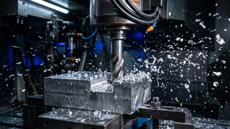
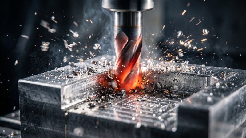
How can you successfully create a perfectly sharp inside corner on a CNC milling machine when rotary tools naturally leave a rounded edge?
Because a rotating cylindrical end mill physically cannot cut a true 90-degree internal angle, manufacturers cannot mill it directly. Instead, machinists must modify the CAD design using dog-bone or T-bone corner reliefs to accommodate square mating parts. Alternatively, they can utilize secondary manufacturing processes like Electrical Discharge Machining (EDM) or broaching to achieve an absolute zero-radius corner.
Modifying CAD Designs with Corner Reliefs
How do you fit a perfectly square block into a machined pocket when the spinning tool always leaves a rounded edge?
To fit a square connecting part into a milled pocket, engineers must modify the CAD model by adding corner reliefs. Because a round cylindrical end mill cannot physically carve a sharp 90-degree internal angle, designers intentionally cut slightly past the corner. This strategic overcut removes the leftover metal that blocks the square part, allowing it to slide into the pocket without requiring expensive alternative machining processes.
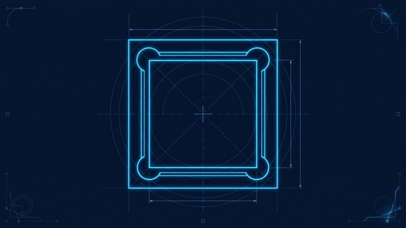
Implementing Dog-Bone Reliefs
A dog-bone relief pushes the cutter outward at a 45-degree angle directly into the exact corner. Consequently, the final cutout visually resembles the shape of a traditional dog bone, featuring circular arcs at the vertices.
Why do we use this specific angle? The milling tool must sweep past the actual corner point to clear it entirely. By moving diagonally, the tool removes an equal amount of material from both of the adjacent walls. Therefore, the square mating part can drop into the pocket perfectly without hitting a rounded corner.
Relief Sizing Guidelines
You must size your relief feature carefully in your CAD software. The radius of your dog-bone cut must always be slightly larger than the radius of the end mill you plan to use.
- If you use a standard 0.250-inch end mill, its radius is 0.125 inches.
- Your dog-bone radius must be modeled at least 0.130 inches.
- This extra 0.005-inch gap ensures the corners of the mating part do not bind against the pocket walls during assembly.
Applying T-Bone Reliefs
Unlike the diagonal dog-bone, a T-bone relief extends the cut straight along just one single axis. The cutting tool travels past the corner straight along the X-axis or the Y-axis. Ultimately, this creates a cutout shape that looks like the letter “T”.
When is this method most useful? You should choose a T-bone relief when you need one wall of the pocket to remain completely flat and untouched. For example, if you are milling a precision slot for a linear guide rail, you might need the side wall to stay perfectly straight to ensure accurate alignment. In this case, you push the entire relief cut backward into the rear wall.
This technique successfully hides the overcut if the connecting part covers that specific wall. However, it does remove significantly more material from one side than the other, which can slightly weaken that specific wall.
Utilizing Drilled Corner Clearances
Instead of using the flat end mill to sweep through the corners, you can simply drill holes at each corner before you start milling the pocket. This straightforward method is called a drilled corner clearance.
Think of this process like performing a plunge roughing operation to clear heavy bulk material before a final profile pass. The drill plunges straight down, rapidly clearing the exact cylindrical volume where the sharp corner will be located. Afterward, the CNC end mill easily cuts away the straight side walls between those pre-drilled holes, never having to engage the heavy material in the deep corner.
Why is this a highly effective strategy? Drill bits are designed to plunge straight down into solid metal much faster and safer than standard flat-bottom end mills, evacuating chips highly efficiently. Furthermore, standard high-speed steel (HSS) or carbide-tipped drill bits are often cheaper to replace than solid carbide end mills. Therefore, removing the bulk of the corner material with a drill first saves shop time and drastically reduces tool wear on your expensive end mills.
Corner Relief Comparison Guide
| Relief Type | Cutting Direction | Best Use Case | Visual Shape |
|---|---|---|---|
| Dog-Bone | 45-degree diagonal | Equal wall clearance is required | Symmetrical arcs |
| T-Bone | Single axis (X or Y) | One side wall must remain perfectly flat | Letter “T” |
| Drilled | Vertical plunge | Fast material removal before pocketing | Circular hole |
Employing Alternative Manufacturing Methods
What do you do when a part strictly requires a perfect 90-degree internal angle, and modifying the CAD file is simply not an option?
When design modifications are impossible, machinists must employ alternative manufacturing methods like Electrical Discharge Machining (EDM) or broaching. Rotary milling cutters always leave a physical radius. In contrast, these alternative processes clear the absolute corner using charged wires, shaped electrodes, or linear cutting teeth. Consequently, these methods allow manufacturers to produce zero-radius internal corners for critical aerospace, medical, and tooling components.
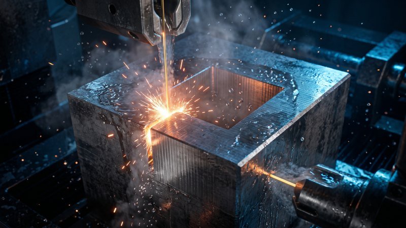
Wire EDM for Through-Hole Sharp Corners
Wire Electrical Discharge Machining (EDM) is a highly accurate non-traditional process. It uses a very thin, electrically charged brass or zinc-coated wire to slice through solid metal. Think of it like a highly precise vertical metal band saw cutting through block stock. However, instead of metal teeth physically scraping the material, a high-voltage spark effortlessly erodes the metal away without any direct physical contact or cutting forces.
Because the cutting wire is incredibly thin—often just 0.010 inches (0.25 mm) in diameter—it leaves a microscopic corner radius. Usually, the final cut radius is merely 0.005 to 0.006 inches. Technically, this is not a mathematical zero-radius angle. Yet, in the manufacturing industry, this small gap is universally accepted as a true sharp corner for nearly all practical assembly purposes.
Wire EDM has one critical physical limitation. The cutting wire must travel entirely through the workpiece from top to bottom. Therefore, this method only works for open-ended through-holes, such as extrusion dies or structural slots.
Sinker EDM for Blind Cavities
What if your square pocket has a solid bottom? This specific feature is called a blind cavity. Wire EDM cannot cut blind cavities because the wire cannot pass through the solid base. Instead, manufacturers must utilize Sinker EDM (also known as Die-sink EDM or Ram EDM).
Sinker EDM uses a custom-shaped solid electrode. Typically, a machinist mills this electrode from blocks of graphite or copper. They machine the electrode into the exact reverse shape of the desired pocket, including the sharp external corners. Next, the machine plunges this electrode straight down into the metal part. The resulting electrical sparks erode away the metal, leaving a perfectly square pocket behind.
This process is absolutely essential for plastic injection molding. Mold makers frequently rely on Sinker EDM to create sharp internal corners for complex tooling cavities. It is highly precise, often holding tolerances tighter than ±0.0002 inches. However, designing and milling custom consumable electrodes makes this a significantly slower and more expensive process than standard CNC milling.
Broaching for Internal Keyways and Square Profiles
Broaching is a traditional mechanical machining method designed for cutting sharp internal features. A broach is a long, straight steel cutting tool equipped with a series of progressive teeth. Importantly, each successive tooth on the tool is slightly larger than the previous one.
As a hydraulic press pushes or pulls the broach through a pre-drilled round hole, each tooth sequentially shaves off a small amount of metal. By the time the final oversized tooth passes through, it leaves a perfect square corner or custom profile. This sequential shaving process is the industry standard for cutting internal keyways inside gears and pulleys.
Unlike EDM, broaching is an extremely fast mechanical process. A machine can finish a profile in just a few seconds per part. Therefore, it is highly cost-effective for high-volume production runs. However, custom broaching tools are expensive to manufacture initially, making it less ideal for low-volume prototypes.
Process Selection Guide
| Manufacturing Method | Best Application | Cycle Speed | Tooling Cost |
|---|---|---|---|
| Wire EDM | Through-holes, extrusion dies | Slow | Low (Standard wire) |
| Sinker EDM | Blind cavities, injection molds | Very Slow | High (Custom electrodes) |
| Broaching | Keyways, high-volume square holes | Very Fast | High (Custom broaches) |
Conclusion
Ultimately, achieving sharp inside corners on a mill comes down to choosing between design flexibility and manufacturing precision. If your product assembly allows for slight overcuts, modifying the CAD file with dog-bone, T-bone, or drilled reliefs is the most cost-effective and efficient solution. However, if your component strictly requires a true 90-degree angle without any design alterations, utilizing alternative methods like Wire EDM, Sinker EDM, or broaching is the necessary path forward.